Page 50 - Clayton's Supply Catalog 2024
P. 50

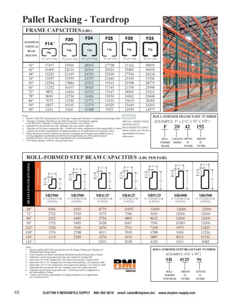
Pallet Racking - Teardrop
                                                                                                                            Pallet Rack
                    FRAME CAPACITIES (LBS.)


                   MAXIMUM        *
                    VERTICAL
                     BEAM      14g.      14g.       13g.      14g.      13g.       12g.
                    SPACING
                            3" x 1 5 /8" COL.  3" x 2 1 /2" COL.  3" x 2 1 /2" COL.  3" x 3" COL.  3" x 3" COL.  3" x 3" COL.
                      36"     17437     23906     28005      27798     31162      38909
                      42"     16400     22610     26364      26020     29481      36692
                      48"     15220     21149     24530      23200     27594      34218
                      54"     13937     19559     22557      21040     25549      31556
                      60"     12594     17884     20502      19163     23398      28775
                      66"     11232     16167     18420      17145     21194      25948
                      72"     9870      14426     16332      15147     18965      23101
                      78"     8683      12794     14406      13030     16842      20448
                      84"     7679      11396     12771      11916     15019      18183
                      90"     6827      10195     11379      10529     13449      16243
                      96"     6101       9160     10188      9533      12095      14577
                  Notes:                                                              ROLL-FORMED FRAME PART NUMBER
                  1.  Based on RMI 2002 Specification for the Design, Testing and Utilization of Industrial Steel Storage Racks.
                                                                                                      1
                  2.  “Spacing” is distance from floor to top of first beam level.  If maximum opening  SPECIAL ORDER ITEMS -  (EXAMPLE: 3" x 2 /2" x 42" x 192")
                    is not floor level, “Spacing” is distance from top of beam to top of beam + 1".
                  3.  Applicable for non-seismic use only.  Building codes may require otherwise.  MINIMUM RUN  F      20    42     192
                  4.  Capacities are for frame components only.  Overall rack system configuration is the responsibility of others.  REQUIREMENTS APPLY.
                  5.  Contact your Tri-Boro representative for design assistance or for applications not covered by above.  Please contact your Tri-Boro
                  6.  Where the bottom portion of frames are exposed to potential minor impacts from forklift trucks or  representative for more
                    moving equipment, consideration should be given to purchasing one of the optional impact  information.
                    protection devices. Ask your Tri-Boro representative for a recommendation.  ROLL-  CAPACITY DEPTH  HEIGHT
                  7.  *F14 Frame capacity: 4,000 lbs. max per beam level.
                                                                                          FORMED  MODEL  IN   IN
                                                                                          FRAME       INCHES  INCHES
                    ROLL-FORMED STEP BEAM CAPACITIES (LBS. PER PAIR)                              7 / 8 2 1 / 2  7 / 8 2 1 / 2
                      BEAM LENGTH (INCHES)  BEAM PROFILE  1 5 / 8 SB2500  2 1 / 2  1 5 / 8 SB3500 3 1 / 2  1 5 / 8 SB4125 4 1 / 8  1 5 / 8 SB4625 4 5 / 8  1 5 / 8 SB5125 5 1 / 8  1 5 / 8 SB6000 6  1 5 / 8 SB6500 6 1 / 2
                                                                                     2 1 / 2
                                                                        2 1 / 2
                                                           2 1 / 2
                                              2 1 / 2
                                                                                    7 / 8
                                                                       7 / 8
                                                          7 / 8
                                             7 / 8
                                 2 1 / 2
                                7 / 8
                                            (3 STUD)
                                                                                    (3 STUD)
                                                                                                              (4 STUD)
                                                                      (3 STUD)
                               (2 STUD)
                                                         (3 STUD)
                                                                                                 (3 STUD)
                                                                       10597
                                                          8775
                                             6910
                                                                                                  12000
                                                                                    12000
                                                                                                               12000
                                4066
                     48"   MODEL NO.  4" CONNECTOR  6" CONNECTOR  6" CONNECTOR  6" CONNECTOR  6" CONNECTOR  6" CONNECTOR  6" CONNECTOR
                     72"        2762         4743         5975         7186         9029         12000        12000
                     84"        2252         4485         5734         6883         8632         12000        12000
                     96"        1735         3483         5028         6067         7596         10583        12000
                    102"        1540         3106         4476         5731         7168          9975        11825
                    108"        1376         2788         4011         5309         6788          9434        11206
                    120"        1115         2283         3276         4330         5887          8512        10152
                    144"                                  2303         3038         4120          6511         8482
                    Notes:
                    1.  Based on MHIA/RMI 2002 Specification for the Design, Testing and Utilization of  ROLL-FORMED STEP BEAM PART NUMBER
                      Industrial Steel Storage Racks.
                                                                                                       1
                    2.  Load Capacities are based on uniformly distributed product load per pair of beams.  (EXAMPLE: 4 /8" x 96")
                    3.  Deflection is based on product load only, and is limited to L(span)/180.
                    4.  Spans from 48" to 80" designed for 25% impact from placing 1 load per shelf.  SB      4125      96
                    5.  Spans from 82" to 120" designed for 25% impact from placing 1 of 2 loads per shelf.
                    6.  Spans from 122" to 144" designed for 25% impact from placing 1 of 3 loads per shelf.
                    7.  Applicable for non-seismic use only.  Building codes may require otherwise.
                    8.  Capacities are for beam components only.  Overall rack system configuration is
                      the responsibility of others.                                         ROLL-   HEIGHT  LENGTH
                    9.  Contact your Tri-Boro representative for design assistance or for applications  FORMED  IN  IN
                      not covered by above.
                                                                                           STEP BEAM  INCHES  INCHES
              48             CLAYTON’S MERCANTILE SUPPLY • 860-350-8216 • email: sales@claytons.biz • www.clayton-supply.com
   45   46   47   48   49   50   51   52   53   54   55